Save to My DOJO
In this series, I discuss some of vSphere’s networking aspects, something you probably have come across when using VMware software. In this first part, I’ll talk mainly about the vSphere Standard Switch (vSS) in context of setting one up and configuring it on a standalone ESXi host (not managed by vCenter Server). I’ll also go over VMkernel adapters, port groups and some of the standard switch settings.
In the second part, I’ll introduce another type of virtual switch called the vSphere Distributed Switch which is only available one vCenter Server has been installed.
The vSphere Standard Switch
A vSphere Virtual Switch, allows a number of virtual machines connected to it to communicate with one another, pretty much like their physical counterparts would when connected to a physical switch. In addition, the vSS bridges virtual networks to physical ones using the ESXi host’s network cards, on which the vSS has been created, as uplink ports to a physical switch.
By default, a standard switch is automatically created when you install ESXi. This is labelled vSwitch0 as per Figure 1.
Note: An uplink port is simply a designated port on a networking device such a switch or a router that connects or cascades one piece of networking equipment to another. Figure 1 shows how the two physical adapters – labelled 3 – on the ESXi host set up for this post have been designated as uplink ports.

Figure 1 – vSwitch0 is automatically created when ESXi is installed.
Looking closely at Figure 1, you should also notice the headings Virtual Machine Port Group and VMkernel Port denoted by 1 and 2 respectively. I’ll explain what these mean in the upcoming sections.
Port Groups
A port group, as the name implies, is a grouping of switch ports. By applying a network policy to a port group, one can enforce security and traffic shaping rules. Additionally, if you have VLANs set up on your physical switches, you can assign a VLAN ID to a port group such that any VM on it will, for all intents and purposes, reside on that specific VLAN.
When you create a network-enabled virtual machine, you are in fact connecting its virtual adapters to one or more port groups. Figure 2 illustrates this aspect. The VM properties, including the selected port group, are shown on the left side of Figure 2 while the switch settings – where port groups are defined – are shown on the right. In this instance, I created two vSphere standard switches each having a distinct port group. Notice how each switch has its own dedicated uplink (vmnic0 and vmnic1).
TIP: If there’s a need to isolate one or more virtual machines from the rest of the network, whether physical or virtual, you can simply create a standard switch with no specified physical adapters (uplinks). Any virtual machine placed on the switch’s associated port group will still be able to talk to any other VM on the same port group but will be completely cut off from other networks. Such a setup comes in handy whenever you need to replicate, say, a live environment in keeping with the same layer 3 addressing (IPv4/6) but without impacting any of the production systems.
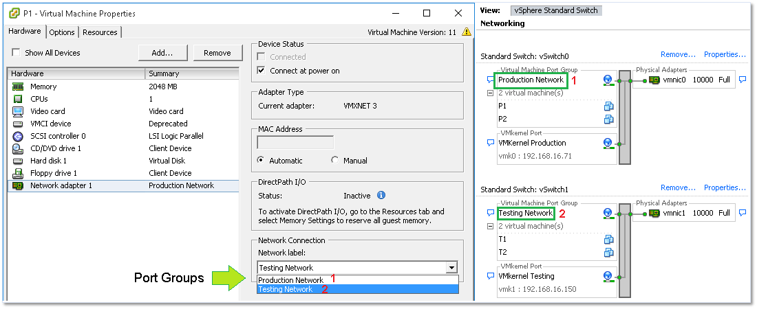
Figure 2 – Assigning a VM to a port group (Left) and port groups created on a standard switch (right).
The VMkernel
The VMkernel network interface, adapter or port is basically a service provider used by the ESXi host to communicate with the outside world and the rest of the VMware based infrastructure. VMkernel adapters are created according to the type of services required by vMotion, Fault Tolerance, Management or perhaps vSAN. A list of services necessitating of a VMkernel are depicted under Services in Figures 3 and 4. A VMkernel is assigned an IP address using either DHCP or one which is assigned manually, the latter option being, in my opinion, the most sensible one.
By default, vmk0 is the first VMkernel adapter created which is enabled for management traffic. Interestingly enough, you’ll still be able to connect to ESXi if Management is ticked off.
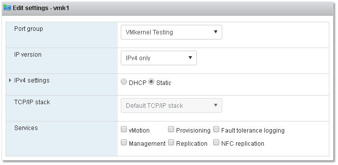
Figure 3 – Using the VMware Host Client on ESXi 6U2 to manage a VMkernel.
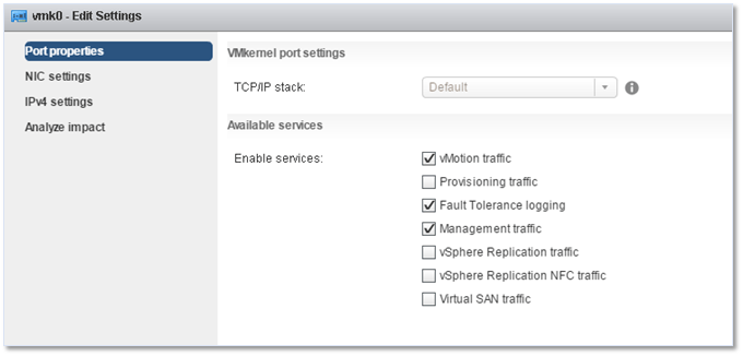
Figure 4 – Using the C# vSphere client to manage a VMkernel.
After creating a VMkernel you’ll come across something that looks like a port group but not quite. This is, in fact, a port. Depending on the tool used to create it, things can get somewhat confusing. For instance, when using the C# vSphere client, you’d be forgiven for thinking that the VMkernel is, in fact, a port group since the same icon is used for both (Figure 5).
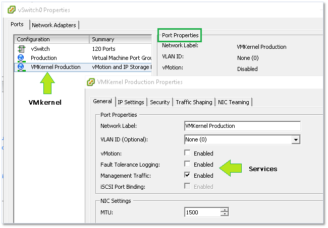
Figure 5 – VMkernel properties as viewed from the C# vSphere client
vSphere Networking Maximums
Before I move on, I’m going to list a few vSphere 6.0 maximums related to standard switches. You will find the full list here.
- 512- Port groups per standard switch.
- 1016 – Maximum active ports per host.
- 4096 – Total virtual network switch ports per host.
- 4088 – Virtual network switch creation ports per standard switch.
Creating a virtual standard switch
There are a number of ways to create a standard switch. These include PowerCLI, ESXCLI, the standard and Web vSphere clients and the recently introduced VMware Host Client assuming you’ve made the transition to ESXi 6.0 update 2. Here’s a quick rundown.
ESXCLI
Use something like putty to SSH to the ESXi host and run the following command to create a 24 port switch called myVSS.
esxcli network vswitch standard add -P=24 -v=myVSS
PowerCLI
Connect to the ESXi host using the Connect-VIServer cmdlet and then issue the following to create the same switch as per the ESXCLI command.
New-VirtualSwitch -name myVSS3 -NumPorts 24
Note: Starting with ESX 5.5, switches are created elastic meaning there is no need to specify the number of ports since these are added dynamically as required. I’ve included the parameter just for completeness sake. In fact, in the case of PowerCLI, the ports parameter is completely ignored.
Thick vSphere Client
When using the vSphere clients, simply highlight the ESXi host on which you want to create the switch, change over to the Configuration tab and click on Add Networking as shown in Figure 6-9. Next, choose Virtual Machine (if this is not misleading, I don’t know what is) binding it to a physical nic as well as creating a new port group for it.

Figure 6 – Adding a new vSwitch using the vSphere client
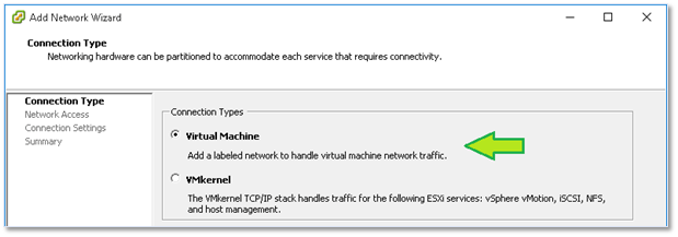
Figure 7 – Choosing Virtual Machine to create a virtual switch
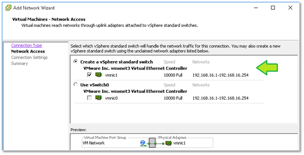
Figure 8 – Binding the virtual switch to a physical nic on the ESXi host (uplink)
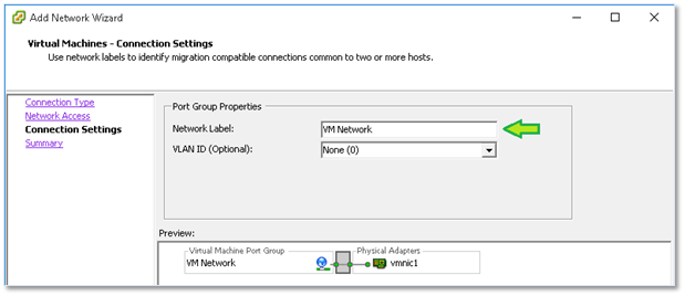
Figure 9 – Assigning a port group label and VLAN ID
VMware Host Client
If you have ESX 6.0 U2 (or have installed the fling) you can also use the VMware host Client to create a standard switch. Once you log in, select Networking from Navigator and switch to the Virtual Switches tab. Click on Add standard virtual switch and fill in the details. It’s as simple as that.

Figure 10 – Using the VMware Host Client to create a standard switch
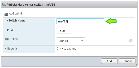
Figure 11 – Finalizing a standard switch using the VMware Host Client
Configuring a standard switch
For this section, I’ll be using the C# vSphere client and an ESXi 6.0 U2 setup. Just as a reminder, vSwitch0 is created automatically as part of the ESXi installation process.
To view the switch’s configuration, highlight the host’s IP address or hostname, select the Configuration tab and select Networking under Hardware. Click on Properties as shown in Figure 6.
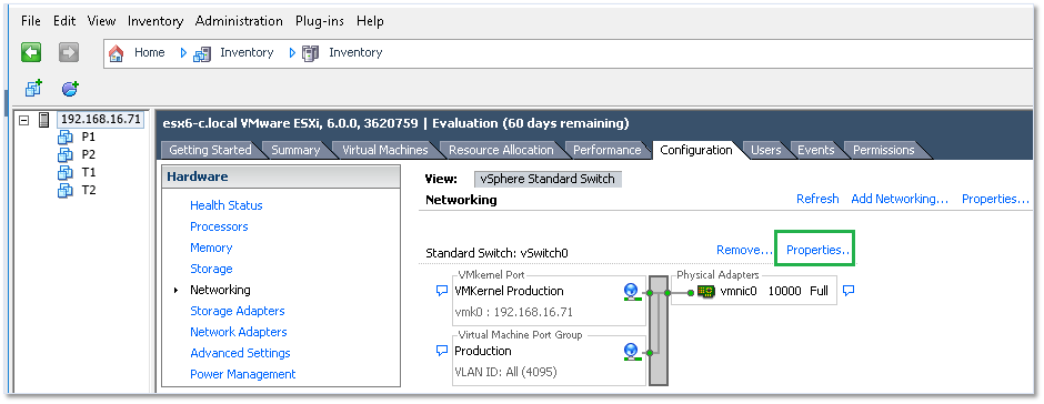
Figure 12 – Viewing the configuration of a stand switch
On the next screen, you’ll find 2 tabs, one called Ports (probably for lack of a better name) and another called Network Adapters. I’ll start with the latter since I’ll refer to it later on. This is basically where you will bind the physical ESXi host’s network cards to the virtual switch. Binding two or more NICs will provide for link aggregation and failover options.
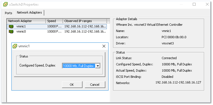
Figure 13 – An ESX’s network cards used as uplinks by the virtual switch
Under the Ports tab – as far as vSwitch0 is concerned – you’ll find three items created automatically when ESXi was first installed. These are the vSwitch configuration, a default port group and a VMkernel. You’ll be able to add other port groups and VMkernels using the Add button at the bottom of the vSwitch properties window.

Figure 14 – Viewing the vSwitch properties such as the number of ports and MTU size
Once again, things can get a little bit confusing depending on the client or method used to create and manage networking. As shown in Figure 15, you’ll need to select Virtual Machine as the connection type if you want to create a new port group.
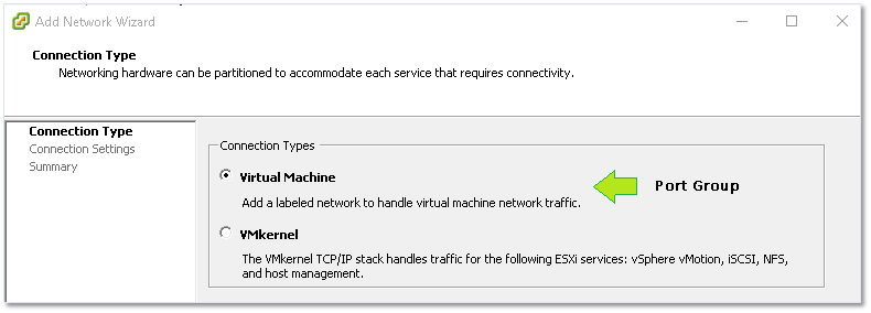
Figure 15 – Creating a new port group
To view the virtual switch settings, just click on the Edit button. Here you’ll find 4 tabs related to the switch’s network policy comprising various options and settings that govern both the switch and how it handles traffic. Again, depending on the tool used, some options may or may not be available. For instance, NIC Teaming is unavailable when using the VMware Host Client (at least, I wasn’t able to find it listed anywhere).
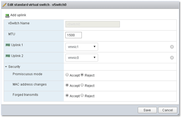
Figure 16 – Viewing the vSwitch settings using the VMware Host Client – No NIC Teaming option
Standard Switch Settings and Policies
The switch’s configuration is accessed by clicking on the Edit button while the vSwitch configuration item is highlighted. This brings up a window with the previously mentioned tabs. Keep in mind that the settings and options set at the vSwitch level will percolate down to every other item in the configuration list. That said, an override option is available for each and every item.
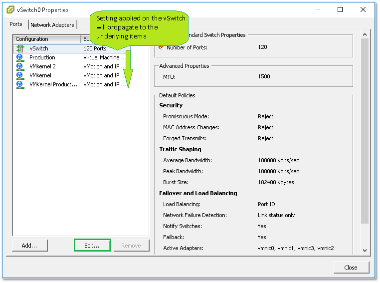
Figure 17 – Settings set at the vSwitch level propagate downwards
Let’s go over the settings / option found under each tab.
General
Here you’ll set the number of switch ports required (max. 4088) and the MTU (Maximum Transmission Unit) size. The latter is generally changed if jumbo frames are enabled on your networks.
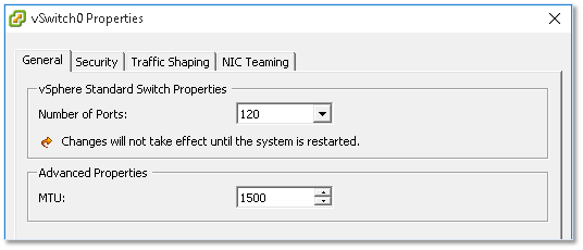
Figure 18 – General settings for a vSwitch
Security
Under the Security tab, you’ll find 3 settings defining the security policy for the switch.
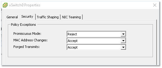
Figure 19 – Security settings for a vSwitch
The settings available are as follows;
- Promiscuous Mode – If set to accept, any VM on the switch having a virtual adapter in promiscuous mode will be able to eavesdrop on all the traffic passing through the switch.
- MAC Address Changes – Determines what happens when the MAC address of a network adapter on a VM is changed. If set to Reject, all traffic emanating from the VM is dropped when the MAC address supplied does not match that found in the VM’s vmx configuration file.
- Forged Transmits – If set to reject, frames with spoofed source MAC addresses will be dropped.
Traffic Shaping
The traffic shaping policy, if enabled, regulates bandwidth and burst size on the switch. This may come in handy when a number of port groups are created on the switch and you wish to apply a traffic utilization baseline across all port groups. Yet again, such a policy can be overridden if required for each and every port group.
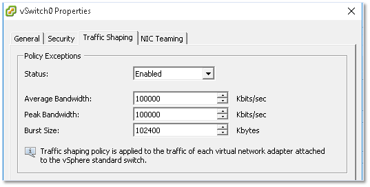
Figure 20 – Traffic shaping settings for a vSwitch
NIC Teaming, Failover and Load Balancing
If you have 2 or more physical ESXi NICs bound to a virtual switch, you will be able to increase bandwidth availability using either Ether Channel or Link Aggregation Control Protocol (LACP). This may require familiarity with some advanced networking concepts (depending on your background) which I’m not going to discuss here. However, this is a great article which goes into great depth on how to configure ESXi to leverage LACP and EtherChannel as implemented on Cisco and HP switches.
Under the NIC Teaming tab you’ll find a number of failover options. In the example below, I have two physical NICs set up as Active Adapters. This ensures that the uplink is maintained if any one adapter goes offline. I could also move one adapter to the Standby Adapters group. When you do this, the standby adapter will only become active when all the NICs within the Active Adapters group fail.
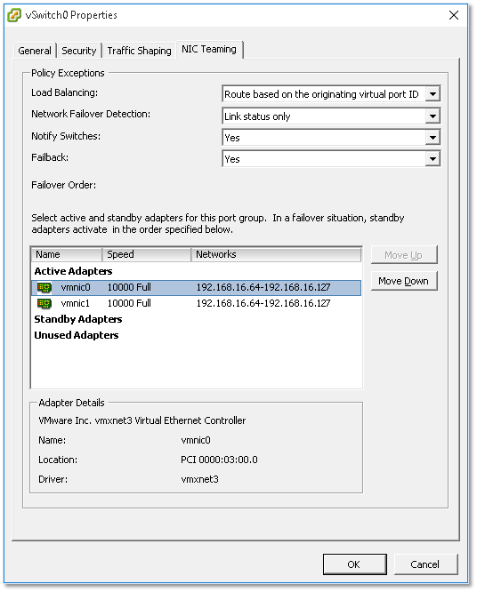
Figure 21 – Teaming and Failover vSwitch settings
Configuring a port group
Most of the settings just covered equally apply when configuring a port group, the main difference being those found under the General tab.
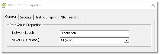
Figure 22 – Setting the port group name and VLAN ID
The Network Label setting is self-explanatory. This is the name you assign to the port group and is what you see listed when you connect a VM’s virtual adapter to a network. The VLAN ID setting is on the other hand slightly more interesting albeit optional. If you have VLANs set up on your physical switches, ESXi operates in 3 different ways to take VLANs into account, these being;
- External Switch Tagging (EST) – This is required when VLAN tagging of packets is performed on the physical switch. The ESXi host’s network adapters are in this case connected to access ports on the physical switch. The VLAN ID must be set to 0.
- Virtual Switch Tagging (VST) – Contrary to EST, all VLAN tagging is carried out by the virtual switch before leaving the host. Host network adapters must be connected to trunk ports on the physical switch. Port groups connected to the virtual switch are assigned a VLAN ID between 1 and 4094.
- Virtual Guest Tagging (VGT) – With VGT, all VLAN tagging is done by the virtual machine. VLAN tags are preserved between the virtual machine networking stack and external switch when frames pass to and from virtual switches. Host network adapters must be connected to trunk ports on the physical switch. For a standard switch, the VLAN ID of port groups with VGT must be set to 4095.
Configuring a VMkernel
There are 2 main aspects to configuring a VMkernel, its IP address and the services it provides. Under the General tab, you can specify a name for the VMkernel, the services provided as well as an MTU value if you’re using anything other than the default value of 1500. Under the IP Settings tab, you’ll find settings for the IP address and network mask. The remaining tabs are again identical to the ones previously covered with all the settings being inherited but which can nevertheless be overridden.
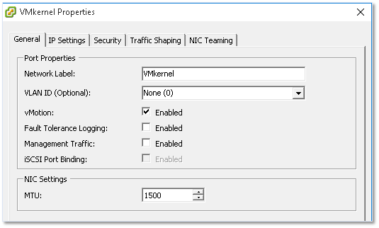
Figure 23 – Setting up a VMkernel
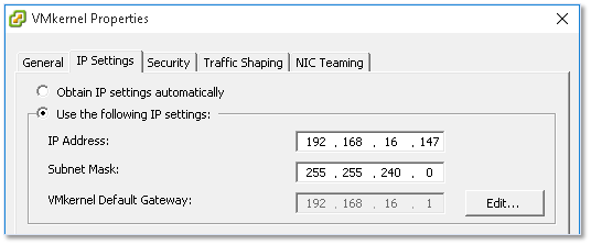
Figure 24 – Assigning an IP address and subnet mask to a VMkernel
Conclusion
This concludes the first part of the series. I think I covered the salient aspects of vSphere standard switches and even though there’s probably more than can be said, I need to draw a line somewhere lest this ends up being one ginormous post.
In part 2 of this series, I’ll cover distributed switches, a useful feature when managing multiple hosts via vCenter Server, and anything else that might have fallen between the cracks.


Not a DOJO Member yet?
Join thousands of other IT pros and receive a weekly roundup email with the latest content & updates!


37 thoughts on "vSphere Networking Basics – Part 1"
Awesome article… Eagerly waiting for a talk on DVS.
Thank you. DVS article should be out soon so stay tuned!
Jason
DO U HAVE THE LINK FOR DVS ARTICLE ?
Here you go;
Really nice one
Thanks. Glad you like it.
Jason
One of the best article ever on the internet about VMWARE. Thank you for all your effort. I hope you continue this job.
Wow! Too kind but still, greatly appreciated.
Thanks
Jason
Thanks, this was exactly what I was looking for. Although as a VMware noob I wish I would have found it 2 hours ago when I started setting everything up! 🙂
I couldn’t understand why I couldn’t tie my VM’s management port to the “Management Network” that had been conveniently created by vSphere on install (maybe they should have picked a different name for a PORT that’s not a NETWORK….).
So I guess then unless you connect a standard switch to a real physical switch and that needs to trunk/distribute VLANS, there’s not really any point in having more than ONE port group per standard switch, right? (As all VMs will be able to talk to each other anyway, defeating the purpose)
Well, rephrasing, *if you also need external connectivity* there’s no point in the above… If you don’t, it still segregates VMs to their port group is you use VLAN IDs.
Hi Walter,
Glad you found the article helpful. The short answer is that multiple portgroups, each with their own id, on the same vswitch are required to enable vms to talk externally to other resources on whichever vlan they reside. So, having multiple portgroups on a single vswitch is commonplace but only when you have a L3 physical device doing the routing. As it is, a vswitch is just an L2 device, meaning it can only perform bridging. Having said that, I am no networking guru, so I hope this explanation was clear enough.
Jason
How can I move the physical NIC from one vSwitch to another? I could not find any way to do it, either by web interface or by vSphere. I’m on ESXi 6.5.
Hi,
Basically, I’m removing a nic from vswitch0 by deleting it and attaching it to vswitch1. Of course, you will lose connectivity if this is your only nic.
Hope this helps.
Jason
Hello, just read your article. We have 2 ESXi 5.5 hosts and both have a few VMs on them. We have 3 vSwitches. 1 for external access and host management, 2nd for fiber storage connectivity, and 3rd for the VMs. Everything was working great until a recent reboot. Now, none of the VMs have internet access as we could connect via teamviewer before.. don’t know what happened. Anything we can look for before wiping everything clean and re-installing?
Hi,
Apologies for the late reply. The only thing that comes to mind is that you had the ESXi firewall disabled or applied a non-persistent firewall rule which got removed once the host rebooted. Other than that, I suggest checking the firewall rules on the physical FWs (if any) for any recent changes.
regards
Jason
Excellent Article, Very well explained. Thank you !
Thank you! Appreciated.
Jason
link to DVS?
https://www.altaro.com/vmware/vsphere-networking-basics-part-2/
Thanks
Jason
Thank you so much.. Please let me know if you have any more learning concepts in VSphere.
I am a student and need an answer to this question. A virtual switch must contain at least on vmkernal port?
No!
Jason…. Being Windows L3 knowing VM infrastructure was mandatory but was never able to understand this VM networking stuff from many years but your this post clear many of my doubts and now my understanding is more clear though not actively working as Windows L3 but an DR SRM tech now.
Amit,
Jason did an amazing job (as always). Glad to hear this was helpful to you.
Hello, a really very good article. If this is part 1, is there a part 2?
Hi Richard,
You can find part 2 here: https://www.altaro.com/vmware/vsphere-networking-basics-part-2/
Very Helpful Article …. I was looking for this kind of content very informative … by the way I could not find Part 2 is still being prepared..
Hi Raj,
Glad you enjoy the article. You can find part 2 here: https://www.altaro.com/vmware/vsphere-networking-basics-part-2/