Save to My DOJO
Table of contents
In many ways, this particular post won’t have a great deal to do with Hyper-V itself. It will earn its place in this series by helping to clear up a common confusion point I see being posted on various Hyper-V help forums. People have problems moving traffic to or from virtual machines, and, unfortunately, spend a lot of time working on the virtual switch and the management operating system.
- Part 1 – Mapping the OSI Model
- Part 2 – VLANs
- Part 3 – IP Routing
- Part 4 – Link Aggregation and Teaming
- Part 5 – DNS
- Part 6 – Ports, Sockets and Applications
- Part 7 – Bindings
- Part 8 – Load-Balancing Algorithms
Ports
From the previous parts of this series, you should now have a basic understanding of how traffic moves between computers using the TCP/IP protocol suite. Rarely is traffic simply between two computers, though. Usually, specific applications are communicating. Web server and web browser, SQL server and business client, control system and telnet client. All of these applications could be running on any given system simultaneously (you should probably separate the servers, though). Because so many network-enabled applications could be co-existing, it’s not enough for a computer to just fire packets at a target IP address. More is necessary in order for those packets to find their way to the destination application. The answer to this problem is the port.
Ports are used with the TCP and UDP protocols and are really nothing more than a numerical identifier that’s in the header of the packet. A server (piece of software) will tell the system that it wants to process all incoming TCP and/or UDP traffic tagged with that specific port number. This is known as listening. Of course, most communication is two-way. So, in addition to the destination port, the packet also contains a source port. When the server responds to the client, it will use that destination port.
Ports are allotted 2 bytes in the packet, giving them a range of 0000 through FFFF in hexadecimal or 0-65535 in decimal. I wasn’t around for the discussions on this, but 65535 is the maximum value for an unsigned 16-bit integer, and 16 bits was the largest integer size that was universally common among processors during the rise of IPv4, so I suspect a correlation.
According to standards, this 2-byte range is broken into three groups: system ports (commonly referred to as well-known ports) are in the range of 0-1023, user ports are from 1024 to 49151, and dynamic ports start at 49152 and run the series out at 65535. The first two are controlled by the Internet Engineering Task Force (IETF) and I personally feel they are somewhat misleadingly named. The IETF retains rigid control over the so-called system ports, but they are not reserved for operating systems or anything like that. They are for common services, such as web and telnet. Anyone can apply to the Internet Assigned Numbers Authority (IANA) to have one of the user ports assigned to his/her application or service, such as 5900 for “remote frame buffer”, which is the protocol used by VNC. The final range is open for pretty much anyone to use for anything.
You’ll notice that the previous paragraph opened with the qualifier of “standards”. That’s because there’s really no way to enforce what happens on any given port. Port 80 is “well-known” to be the port for web servers to use, but it’s trivially simple to code any application to listen on that port or any other.
I promise you some pictures and further explanation, but I think this is a great place to segue into a discussion of sockets.
Sockets
Ports are nice, but they can only get you so far. An application can register a port, but that just facilitates communications. A port alone does not a communications channel make. This is where the socket comes in.
Sockets are a simple thing. They are the point of contact for a network-enabled application on a computer. Sockets have their own addresses, which are just a combination of the IP address of the host and a specific port. They are what makes TCP and UDP communications possible. In order for proper communication to occur, a TCP or UDP packet requires a destination socket address. Let’s examine the flow:
Problem: A user wants to retrieve a web page from the Altaro web site. He types http://www.altaro.com into the web browser and presses the Go button.
- From the above, the web client knows two things: the user wants the default page from www.altaro.com on the http protocol.
- The first thing it does is resolve the hostname www.altaro.com to an IP address using DNS: 64.91.230.229
- Because the user specified http, it knows to use port 80.
- Therefore, the destination socket is 64.91.230.229:80.
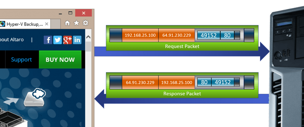
The destination portion of the packet is now ready for transmission. But, that’s not quite enough. Since the user is asking the web server to deliver a web page, the target server needs to know where to send that page data. The mechanics to handle this are built right into TCP and UDP. The source system first inserts its own IP address in the source IP portion of the packet. Next, it produces a number from the range of dynamic ports (usually at random), and inserts that as well. That’s the source socket. The packet that it sends out looks like this:
 As you’ll recall from previous discussions, traffic doesn’t really move in a message-response fashion. It’s all a send operation. So, what happens is that the destination application is provided with the source socket information. Remember how I said that the OSI model is just a model and that practice is always different? This is one of those places. The complete layer 3 packet doesn’t necessarily survive all the way into layer 7, but the application layer is aware of both the source IP address and the source port. So, when it processes the request and wants to send back a “reply”, it simply reverses the way the socket information was placed in the packet that it received. Outside the contents of the data portion, the packets going back to the source will be the inverse of those coming in:
 What you’re seeing above is the motion of traffic between two sockets. A server application will always have a socket prepared for incoming traffic. This is called listening. A listening socket doesn’t care where the packet came from. It only cares that it was sent to the socket’s address. The socket belonging to the originating client application, however, will (or should) only accept traffic on its socket that is an inverse match for the request that it made. By maintaining a hash table of the destination socket addresses and dynamic source ports that it has made requests on, the application can easily manage multiple connections to multiple destinations. By maintaining a hash table of the sockets, a host can easily manage the traffic for multiple server and/or client applications.
Network Address Translation
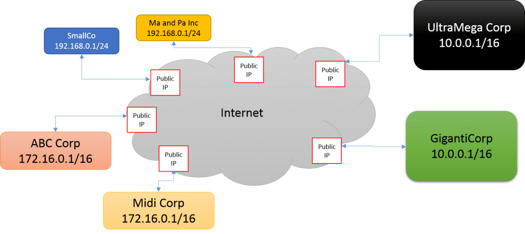
There is one inaccuracy in the sample image illustrating the communications chain. The source IP that I used is from a private range. These ranges (10.0.0.0/8, 169.254.0.0/16, 172.16.0.0/12, and 192.168.0.0/16) are not allowed on the open Internet. Any packet with one of these addresses as a source or destination will be dropped by the first Internet router that processes it.
The purpose of these private ranges is to address IP address starvation. Within IPv4, there aren’t nearly enough addresses for every device worldwide to have its own. But, any organization is free to use private ranges, as its guaranteed that duplicate addresses in these spaces cannot collide across the Internet. Organizations then link up to the rest of the Internet using just one or only a few public IPs.
 In the above diagram, all six of those companies, all of various sizes, connect to the Internet consuming only a single public IP address apiece. Their internal networks are much larger, and some even use the same addressing scheme as other corporations. Network address translation (NAT) is the technology that facilitates this, and it’s very easy to understand.
When a web browser sends a request to a web site, it can remember all the socket information that was used in the request. When a packet comes in with the socket information reversed, that’s how it knows that it has received a response to that particular request.
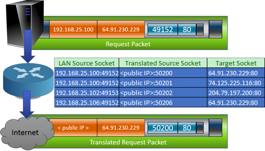
 This is the same concept that NAT operates upon. The web browser sends its packets out, where they eventually reach the router that divides the private network from the public Internet. Unlike a standard router, a NAT router is going to make modifications to the layer 3, and possibly even the layer 4, portion of the packet.
 Just like the requesting application builds a hash table out of the source port and target sockets in order to match incoming packets with requests, the NAT router keeps its own table comparing source sockets, destination sockets, and its own replacement source sockets. The router won’t always need to replace the source port, but it often will in order to prevent collisions from multiple source machines attempting to connect to the same target IP using the same source port. When a responding packet is received that is an inverse match for an item in its table, the NAT router performs the same replacement in reverse so that the sending application can also correctly identify incoming packets.
Application to Hyper-V
Hyper-V is largely unconcerned with most of what we’ve talked about in this article. The significance is that some people seem to become agitated when they learn that the Hyper-V virtual switch is a switch, not a router. It can, and does, perform the MAC address replacements that we saw in part 3, but it doesn’t track source and destination ports the same way. In fact, barring the use of an extension, the only way Hyper-V becomes at all concerned with ports is if you establish ACLs. These ACLs allow you to selectively allow or deny communications to/from specific ports, among other criteria.
While the virtual switch is probably Hyper-V’s biggest network component, that’s certainly not all it does. Many of its other functions are facilitated by SMB, which uses the well-known port of 445. The management operating system also needs network communications to function, just like any other Windows installation. If you poke around in the default firewall rules, you’ll find a number of important services, such as those belonging to remote access applications.
What’s Next
In the next installment in this series, I’m going to refresh an older post about bindings in Hyper-V.


Not a DOJO Member yet?
Join thousands of other IT pros and receive a weekly roundup email with the latest content & updates!


11 thoughts on "A complete guide to Ports, Sockets and Applications in Hyper-V"
I think there’s a mistake in your last diagram.
Lan source socket should be 192.168.25.100:49153 for the Target socket 74.125.225.116.80.
Likewise for the Lan source socket 192.168.25.100:49154 for the target socket 204.79.197.200:80.
This is based on the diagram just above it (tab 2 and tab 3).
Sorry I didn’t finish reading, you did write this:
“The router won’t always need to replace the source port, but it often will in order to prevent collisions from multiple source machines attempting to connect to the same target IP using the same source port.”
Nevermind then!